|
|
Maintaining Evinrude
Lightwin - Ducktwin
- Yachtwin
1952 - 1968 , (Information & Observations) |
|
, Evinrude, OMC, outboard motor, outboard motor repair, 9.9, 15 hp, date/year of manufacture, water pump, carburetor, long shaft, 15 hp conversion, sailmaster
|
|
Maintaining Evinrude
Lightwin - Ducktwin
- Yachtwin
1952 - 1968 , (Information & Observations) |
|
One thing that I want to convey here is that I write
only on motors that I have actually worked on, which relate to, over a period of MANY years, consisting of many THOUSANDS
of hours, and then more in maintaining/updating these articles. They are
motor specific, HOWEVER if you are having a diagnosis issue, my Trouble Shooting
article covers MANY more aspects that may help you diagnose your issue.
CLICK
HERE for access to that
article.
First off, here, maybe I had better explain the models designations, this being the 3 HP. The Evinrude labels these models Lightwin, Ductwin and Yachtwin, being an extension of their other series/sizes of motors, (5HP = Angler, 5.5/6HP = Fisherman, 7 1/2 HP = Fleetwin, 9.5/10 HP Sportwin, 15/18HP Fastwin, 28 HP = Speedtwin, 33 HP = Ski Twin, and 40HP = Big Twin). The "Twin" referring to two cylinders.
The Lightwin and Ductwin utilized an angled "Weedless" gearbox of 110 degrees
and a outer lower weed deflecting keel at 135 degrees. The Yachtwin had a
standard 90 degree gearbox.
The Johnson used a model "J", for this series with the JW being the
Weedless gearbox and the JH as the Heavy Duty standard gearbox.
There has been confusion (for me at least), on these models, but I think that I have finally somewhat figured it out. Normally in the era after this, (that we are more exposed to) Evinrude and Johnson were the same motors, just a different color. BUT here, this motor appears to be the start of that style, with a blend of the two companies where they shared the powerhead, carburetor, steering, clamping bracket and lower units, but different gas tanks, sideplates and starters.
However, the main difference was the Evinrude which appears to have been (what they thought as a DELUXE model) with an older style cast aluminum lower sideplates, which also incorporate the front carrying handle, and a slightly different gas tank along with a associated starter assembly. The Johnson was a more of a PLAIN JANE with a stamped, single shaped wrap around sheet aluminum sideplate similar to their previous T models. The front carrying handle is bolted onto the sideplates. And colors changed a lot. In the photos below, notice the fuel shut off valve is at the rear on the Evinrude, and nearer the front on the Johnson.
|
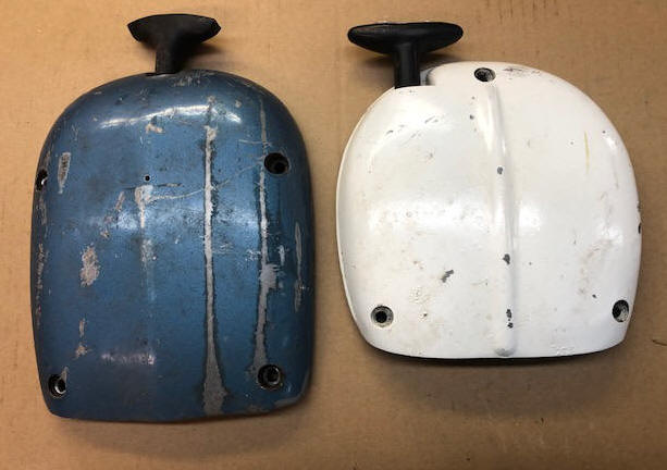
Here in the
LH side of this photo you see
the Evinrude starter from the top, And the Johnson starter unit to the right side |
 |
The bottom side of these starter housings contain the ratchet/pawl system that engages the flywheel to rotate the flywheel during the starting mode. Here, the first three years for both motors were different from the later version, as both being seen below. The later style was considerably simpler and more reliable. In the photo below the image on the right signifies the engagement style for both Evinrude and Johnson starters from 1955 on.
|
Here you see
the Evinrude starter from the underside on the left, And the Johnson starter unit to the right side |
 |
| Here you see a close up of the earlier starter pawl system |
 |
|
Here you see
what appears to be a restored
1952 Johnson JW10 |
 |
| Here you see a 1956 Evinrude Lightwin | Here you see a restored 1957 Johnson JW13 |
 |
|
Even though OMC owned Johnson and Evinrude after the merger in 1935, they operated as two independent companies as for manufacturing outboards for a number of years. It wasn't until about 1960 that the product line began to merge and then the only difference then was the color of the motor. So this series appears to be the first of the Evinrude designed 3 hp that also incorporated many of the proven Johnson ideas. Here it seems the midsection/clamp unit, lower unit and bare powerhead were Evinrude and about all other than the carburetor was Johnson, with a lot carrying over from the Johnson TN series The starter unit was a somewhat improved carryover for the first three years and then greatly improved in 1955.
After that, they seemed to benefit from joint engineering and then utilized a lot of parts interchange even between models and HP of closely associated motors in those days as it was simple to create "Families" of near HP size motors, many using the same parts. For example this motor used the same carburetor as was used on the 1.5hp and the 4hp, (the outlet throat was the same diameter for all, thereby using the main-jet and reed valve plate entrance hole as the determining factor for fuel supply). The magneto internals were also from 1.5hp up to 40hp. Also water pump impellers shared numerous models.
All the engine specs are the same for either brand. The motor unit, magneto, clamp and all lower shaft/gearbox are interchangeable, the difference is in the fuel tank, it's mountings, side skirts and the starter unit.
Statistics For These Motors :
These motors develop 3 hp @ 4000 RPM
Cylinders
2
Bore diameter
1.560"
Stroke 1.380"
Displacement 5.28 CI
Bearings, bronze bushings, both mains & rod
Johnson Tillotson type carburetor with
butterfly choke, throat dia. .612" - Carb kit Sierra 18-7043
High speed jet, adjustable up until 1963, Fixed after that,
Starting point 1/2 turn out
Idle jet - 1 1/4 turns out as a starting point
Fuel cap. 7 pints ;
Remote tank with fuel pump as an accessory, & standard for 1968
on
Fuel mix is Oil 1/3 pt. (22 :1) SAE-40 per Gal
Point gap is .020"
Plug gap .035", Champion J4J or J6C spark plug.
Flywheel key - Woodruff .154" (5/32") wide x .235" thick x .603" long
Flywheel nut - 7/16" NF, -- 11/16" wrench size
Water Cooled - rubber vaned impeller type - Sierra #18-3001
Gearbox oil - 90 W gear oil
Gear Ratio - Weedless 12-20 (1.666) for 3 blade, 17-28 (1.647) for 2 blade ??
Prop. dia. & pitch- 2 blade 6 1/8" x 6 1/4" for the JW while a 3 Blade, RH, 8" x 5 1/2" for the JH or Yachtwin
Shear Pin - 1/8" X 1.00" OAL, along with a rubber shock absorber hub in prop
Prop nut retainer pin - 3/32"
X 1 1/4" cotter pin
Prop nut, brass slotted- 1/2" NF
acorn nut, with rubber nose cap for later versions
Weight 32# for the JW & 36# for the JH. The Lightwin may weigh slightly more because of cast sideplates.
They were made in 3 main versions for Evinrude, the Lightwin, Ducktwin, and
Yachtwin. The Lightwin and Ducktwin used the
weedless gearbox, while the Yachtwin used the Heavy Duty
Right Angle Drive. They were available with a ridgid shaft
and OR
a folding shaft. The only difference between
the Evinrude name Lightwin and Ducktwin was the color, blue for fishing, brown for the
duck hunters. The Yachtwins followed the Lightwin colors.
The Johnson line colors stayed the same no matter which version..
The Johnson line was JH, JHL, JHF JHFL or JW, JWL, JWF, JWFL. They were also available with a ridgid shaft OR a folding shaft. Here the model was the J series and the W indicated Weedless, the JH series was the standard 90 degree gearbox, but heavier. The L suffix indicated Long Shaft. The folding models could also have been supplied with a plastic molded suitcase carrying case. However not all these models were made during the full production years.
As seen in the photos below, the real difference between the Evinrude and Johnson was the gas tank/starter and the side skirts. Evinrude used 4 screws to hold the starter on and the rope exited in the center. The side skirts were two piece cast aluminum. The Johnson had 3 screws to hold the starter unit on and the rope exited on the RH side. The side skirts were a one piece wrap around sheet aluminum, copied off the earlier 2 1/2 and 5 hp H and T series. The photos below show scarcer folding versions.
You will see the term
Weedless mentioned here, what this applies to is that the propeller shaft is
mounted a downward rearward angle. This is in comparison to the normal 90
degree right angle versions. The reason seems to be that these were
fishing motors and possibly being used in weed infested waters at time.
With the angled prop shaft (and associated gearbox front) in front of the prop,
this was supposed to allow weeds to slide off and below the prop.
| Here you see a 1966 Evinrude Lightwin 3602E folding motor with carrying case | 1967 Johnson JWF folding motor |
 |
 |
| Here you see a better photo of a 1967 Evinrude Lightwin folding long shaft motor with carrying case |
 |
This series of motors underwent NUMEROUS changes during the lifespan of their manufacturing. For the first few years of the Johnson line for this series, they had a lot of the 5hp TN series design but were married to Evinrude's carburetion (which was a improvement). In the most part they apparently were one of the first that used lots of the Evinrude design. However the color for the first few years was the famous sea mist green of the previous Johnson T series motors.
And there seems to NOT be a lot of old parts lists available for the early motors to verify when these changes took place. It took me a few years to run down some (both original and copies). Also spare original parts are getting scarce, and the ones that are left, the price raises as the quantity declines. Aftermarket parts like water pump impellers, points, condensers and coils are still available at a reasonable price.
These 3 hp 2 cylinder 2 cycle motors were made from 1952-1968 and was direct drive, meaning NO neutral, or no F-N-R shifting. So to back up, you rotated the motor 180 degrees. These models could be had in either short (15") or long (20") shaft lengths. Also for the Johnson, the model was J, where the second letter W which means Weedless Drive for fishermen. JH means (Heavy Duty), later called the Standard version, Right Angle Drive which was originally meant for sailboat auxiliary use (apparently heavier gears and different pitched prop) an 8" x 5 1/2", as compared to the weedless prop which used a 6 1/8" x 6 1/4".
Here the name Evinrude Lightwin was carried over into the next generation of 4 hp motors also. But the name Ducktwin appears to have been dropped.
This series engines still used bronze sleeve bearings on the connecting rod crankshaft journals and the main bearings until 1970. Several of our most respected JohnnyRude wrenchers recommend 24:1 WC-3 Full Synthetic oil for pre-1970 3hp engines.
For the first few years of the Johnson line for this series (from 1952 to about 1954) the starter mechanism was different (same overall outer configuration), and the fuel tank mounting plate was a carryover from the TN series.
For 1963 there were some major changes to different steering housing, and to a single clamp screw. This also appears to be where the carb was changed from a adjustable mainjet to a fixed jet version.
1968 appears to have been a year where a lot of experimenting OR
cleaning up the floor sweepings, took place, AND/OR prototyping took place as there
was NUMEROUS models available (like 33 for both Evinrude and Johnson)
The rare Johnson of these 3hp series would be the last year (1968) where
it apparently was a prototype for the 1969 4hp as it used the 4hp upper and
lower cowling, clamping bracket AND starter unit, but was still advertised as a 3hp.
| Here you see the 1968 Lightwin with remote gas tank |
|
|
The later engine blocks were provided
with mounting location for the installation
of a accessory fuel pump for a remote tank.
1968 fuel pump and remoter tank, lower pan cowling, also 1968 last year of production for 3hp, This motor then from 1969 on was again
offered in the Lightwin (but they dropped the Ducktwin), and for Johnson they
went to the ridgid lower unit.
The 1968 3 hp (last year of production for this 3hp) is pretty well a cosmetically different motor, essentially using the J powerhead, pre 64 adjustable main jet carb and modified midsection reverting back to the 2 screw clamp bracket, apparently a cleanup of old parts. The starter was a pivoting up unit mating it's gear into the lower outer flywheel ring. It also sported a fuel pump and exterior tank, which morphed into a 4hp in 1969, same motor just they raised the RPM by 500 to 4500, which had this total different side throttle, fiberglass motor covers and a 90 degree 3hp gearbox. FOR A LINK TO IT, CLICK HERE
Years of Manufacture : In the chart below, for Evinrude, you will see a lot of model numbers for each year, typically as in the 1952-54 span you see #3012 and 3013, here, typically the 3012 is for a short shaft while the 3013 is a long shaft. To further explain, this motor was available in the two versions above AND also in standard straight prop shaft, Weedless, or a folding lower shaft, therefore these other numbers may designate that. The Johnson simply added a letter L to their model number and it appears to not be complete in relationship to the Evinrude list. However since Evinrude was the "Flagship" line, maybe the offerings from Johnson were less.
|
Evinrude Year |
Evinrude Model | Evinrude Version | Johnson Year | Johnson Model |
| 1952-54 | 3012 | Lightwin__SS | 1952-54 | JW-10 |
| 3013 | Lightwin__LS | |||
| 1955 | 3014 | Lightwin__SS | 1955 | JW-11 |
| 3015 | Lightwin__LS | JW-11L | ||
| 3016 | Ducktwin__SS | |||
| 1956 | 3018 | Lightwin__SS | 1956 | JW-12 |
| 3019 | Lightwin__LS | JW-12L | ||
| 3020 | Ducktwin__SS | |||
| 1957 | 3022 | Lightwin__SS | 1957 | JW-13 |
| 3023 | Lightwin__LS | JW-13L | ||
| 3024 | Ducktwin__SS | |||
| 1958 | 3026 | Lightwin__SS | 1958 | JW-14 |
| 3027 | Lightwin__LS | JWL-14 | ||
| 3028 | Ducktwin__SS | |||
| 1959 | 3030 | Lightwin__SS | 1959 | JW-15 |
| 3031 | Lightwin__LS | JWL-15 | ||
| 3032 | Ducktwin__SS | |||
| 1960 | 3034 | Lightwin__SS | 1960 | JW-16 |
| 3035 | Lightwin__LS | JWL-16 | ||
| 3036 | Ducktwin__SS | |||
| 1961 | 3038 | Lightwin__SS | 1961-62 | JW-17 |
| 3039 | Lightwin__LS | JWL-17 | ||
| 3040 | Ducktwin__SS | |||
| 1962 | 3042 | Lightwin__SS | ||
| 3043 | Lightwin__LS | |||
| 3044 | Ducktwin__SS | |||
| 1963 | 3302 | Lightwin__SS | 1963 | JW-18 |
| 3303 | Lightwin__LS | JWL-18 | ||
| 3312 | Ducktwin__SS | |||
| 1964 | 3402 | Lightwin__SS | 1965 | JW-19 |
| 3403 | Lightwin__LS | JWL-19 | ||
| 3412 | Ducktwin__SS | |||
| 3342 | Yachtwin__SS | |||
| 3343 | Yachtwin__LS | |||
| 1965 | 3502 | Lightwin__SS | 1965 | JW-20 |
| 3503 | Lightwin__LS | JWL-20 | ||
| 3512 | Ducktwin__SS | |||
| 3532 | Yachtwin__SS | |||
| 3533 | Yachtwin__LS | |||
| 1966 | 3602 | Lightwin__SS_Folding | 1966 | JW-21 |
| 3603 | Lightwin__LS_Folding | |||
| 3612 | Ducktwin__SS_Folding | |||
| 3632 | Yachtwin__SS_Folding | |||
| 3633 | Yachtwin__LS_Folding | JHLF-21 | ||
| 1966-67 | 3612 | Ducktwin__SS_Folding | JHF-21 | |
| 1967 | 3702 | Lightwin__SS_Folding | 1967 | JWF-22 |
| 3703 | Lightwin__LS_Folding | JWLF-22 | ||
| 3706 | Lightwin__SS_Ridgid | |||
| 3707 | Lightwin__LS_Ridgid | |||
| 3712 | Ducktwin__SS_Folding | |||
| 3716 | Ducktwin__SS_Ridgid | |||
| 3732 | Yachtwin__SS_Folding | |||
| 3733 | Yachtwin__LS_Folding | |||
| 3736 | Yachtwin__SS_Ridgid | |||
| 3737 | Yachtwin__LS_Ridgid | |||
| 1968 | 3802 | Lightwin__SS_Folding | 1968 | JWF-23 |
| 3802A | ?? | |||
| 3803 | Lightwin__LS_Folding | JWLF-23 | ||
| 3806 | Lightwin__SS_Ridgid | |||
| 3807 | Lightwin__LS_Ridgid | |||
| 3832 | Yachtwin__SS_Folding | |||
| 3833 | Yachtwin__LS_Folding | |||
| 3836 | Yachtwin__SS_Ridgid | |||
| 3867 | Yachtwin__LS_Ridgid_ |
This article will ultimately contain repairs to five motors, three Johnsons and two Evinrudes. One Johnson JW10, another JW18, JW19A and a Evinrude 3022, and a 3706 converted to a 3602E folding motor. And then a 3632E Yachtwin folding. Therefore it is hands on information scavenged off repairs to a wide range of this series of motors.
Carburetor ;
Do not think that you can simply spray
automotive carburetor cleaner in the throat and BINGO it
automatically cleans like Mr. Clean. Here you really
need to strip it down a soak them (for a few hours) in a automotive
type carburetor cleaner. Then wash these parts off using
HOT water, blow all the passages out with compressed air and let
them dry.
The main jet is mounted in the bottom fuel bowl
part of the carburetor (also known as the high speed
jet), and was adjustable (protruded as a twistable shaft) up until 1963, after that it was fixed
jet where they simply found a jet diameter hole that was near a
common size, (non adjustable where they simply plugged the adjustable carb hole).
The knobs are different between the Johnson and the Evinrude along
with being changed numerous times during the production span.
These knobs changed colors depending on
the year of production. For the Johnson, the early were
black plastic, later turning into red as seen in the photo below.
The Evinrude, were pot metal and painted, again either black for the
early versions or white as the color scheme added more white to the
fuel tank and tiller handles.
In the photos below, you see a representative of both the front
cowlings showing the adjustment knobs.
| Here you see the early adjustable high speed carburetor | Here the newer fixed high speed carburetor |
These knobs are adjustable on the shaft so that once you find the desired setting, you can reset the knobs to a desired number, (usually #1) if it, (the knob) is round, or have the pointer aligned, usually UP. This is accomplished by the shaft being internally threaded to 6-32, lightly serrated, AND split. The knobs have a bore that fits closely onto this split shaft. A tapered head screw being screwed in after the knob is installed, where this tapered head screw expands the split shaft, tightening the knob in place. If you loose that screw, a easy replacement is one designed as a retainer for electrical outlet covers.
The
normal initial setting for the idle (slow speed jet) would be 1 1/2 turns out
from lightly bottomed out for either style carburetor. Where the normal starting point of the Pre
63 high speed jet would have been probably 3/4 of a turn out.
To start your disassembly, you need to remove the sideplates, for the Evinrude that is a rather straightforward situation as each side comes off independently. But for the Johnson, which uses a wrap around shroud, you may have to remove the steering handle in order to get the shroud off that side.
This carburetor is fairly simple design, being held on by (2) 1/4" nuts (which can be hard to access unless you also prior remove some linkage. There is one throttle arm return coil spring attached through a hole in the carb arm and hooked over a protrusion on the block (LH side) that needs to be removed before the carb removal.
Disassembling the carb on the JW19A motor proved to be troublesome in the fact that the float needle was seized inside the screwed in orifice, which upon trying the upper tab for the return spring became broken off. Now the only way to get that orifice and seized orifice out was to cut a slot in the now broken needle so the orifice could be unscrewed along with the needle. Time for a carb kit that includes those parts. On the second motor JW10, that I own, the original cork float outer seal was so deteriorated, that I heated it with a hand held heat gun, evaporating any liquid, prior to painting it with Testors clear Dope as a sealer.
On reassembly it is best to get a manual showing the parts relationship, (Solec manuals have a good well illustrated section for many different types of carburetors) as by the time you get a new kit shipped in, (and most kits now do not have any instructions) you will have forgotten where and how many washers or needle seals go where.
This carb has an
exit throat diameter of .620" to the manifold. FYI, the manifold inlet
diameter hole is .440". In the photo below, you can see the plugged
high speed jet boss on the lower left.
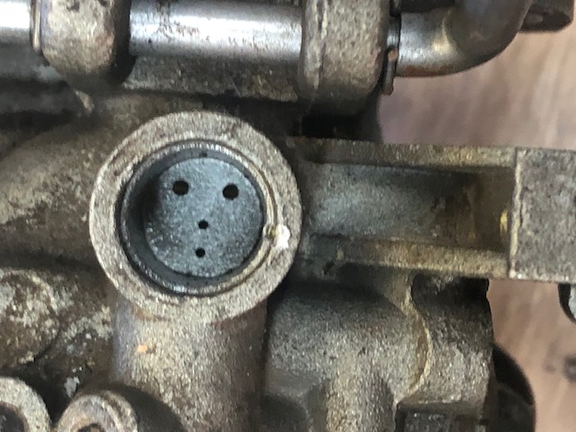
Internally they need to be clean of debris. On
the top there is a expansion plug of 7/16" diameter, under it is a chamber
with 4 small holes that feed the idle to mid-speed. These have to be free
of debris. To remove this plug, use a sharp tool like an ice pick, drive
it in close to one side, (pointing inward) with it driven in, pry the plug out,
revealing the holes below as seen in the LH photo below. The
replacement from the repair kit is slightly dome shaped, to replace it, be sure
the mating seat is clear of debris, place the plug in place and by using a flat
nosed punch (1/4"dia.) tap the dome down, forcing it out and securing it
in the top of the hole. You can reuse the old plug, by hammering it flat
(partly closing the hole you just put in it) carefully fitting
it so it can be snuggly driven into the hole and bottomed out against the inner
flange, then a slight amount of JB Weld, sealing the edges and in the hole works for
me.
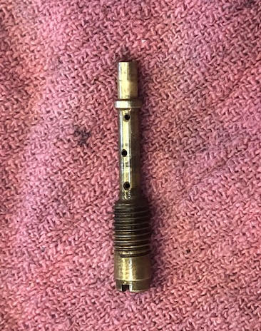
In the LH photo below you can see the small idle/slow speed holes that are in the cavity UNDER the expansion plug described above. In the RH photo, you will see the high speed nozzle, in the shaft above the threads are three small holes that go all the way through both sides, these also have to be free of debris.
| Here you see the holes in the carburetor below the aluminum plug | Here the high speed venturi tube |
 |
 |
I had one carb (a
post 63 non adjustable main jet) give me fits even after installing a new kit.
I tried to remove the main jet that is buried in the bottom of the float bowl.
But it was stubborn, so in order to evaluate if it was open, I tried numerous
drill bits, fine copper wire strands, and finally 25# monofilament fishing line.
This line finally was able to be seen inside the bowl as it had came through the
jet. BINGO, it was
clear, this mono was .021" where
the .025" wire did not go. This is probably meaningless , but just FYI.
| Here you see the carb torn apart before reassembly, and the new kit |
 |
Carb Problems ; On a 1966 Evinrude, after I had rebuilt the carb with a Sierra carb kit, I found that the float valve seat threads were not compatible where the old carb body threads and would not thread all the way in. I guess the Chinese guessed at the threads instead of having specs and the thread numbers were slightly off. So revert back to using part of the original parts. The worst was that after the rebuild and reinstall, when I turned on the fuel shut off valve, it flooded to where gas poured out the carb throat. I will bet that tore that carb apart at least a dozen times, checking clearances for the float, even blew into the fuel inlet while tipping the carb so the float would close. YEP the float was working.
Finally I posted a inquiry on the AOMCI "Ask a Member" forum. Most of the responses were the general HAVE YOU DONE THIS responses. Bingo one response was to check for a plugged float bowel vent. The reason was that with the vent "plugged", there would be a big air bubble inside the bowl, and on top of the float, holding it from not being able to close the shut off needle valve, whereby the gas was pushed up the high speed main-jet and into the throat.
I had already looked for a external vent hole like on numerous other OMC carbs I have worked on, but nothing visible. However on the front of this carb above where the breather bolts on are two 1/8" holes (one on each side) that have a squarish recess on the bottom side, WHY? these have to be the vent holes. So I tore it completely apart, removing the 4 lead plugs. Now by using a two nails that fit inside the now open passages, I tried to find some connection or idea of where the holes went, and how deep. I could not find to where any connected into the float bowl chamber, but by looking up inside a narrow cavity, it appeared there may have been a hole that may have led to one of these channels. But it would be impossible to unplug any blockage here even with compressed air. HOWEVER one hole went straight down from the top, to within about 3/16" of a internal flat boss about the size of a lead pencil eraser inside the upper chamber and directly above the float. So I drilled (extended) that hole all the way through.
If I was to encounter this again on these carburetors, I would not tear it all apart, but simply drill a new hole from underneath (now that I know where my new extended hole came out) and connect it with the longer hole already there from above.
In the photos below you can see ????.
| Here you see the | Here the |
I then reassembled the carb, replaced the lead plugs
and after turning on the fuel valve, no flooding, and it started on
the second pull.
The mystery is with this motor now 55 years old, how/why did
it run before? Maybe the old paper gasket was not tight
or had a crack/leak allowing the bubble to dissipate ???
Or maybe what I saw hid up inside that cavity was a vent to somewhere.
Reed Valves ; Behind the carburetor is the reed valve plate. In the photo below it is viewed from the rear side, showing the stop plates which cover the reeds in this photo. A quick check to see if they operate, is to blow on the front hole that leads to the carb. You should be able to blow enough to open these reeds, and then by sucking, no air should pass back.
In the photo below you will notice a SMALL round hole in the upper section between the reeds. This leads into the cavity where the slinger ring of the crankshaft resides in the block's front 1/2. The front of the hole leads to the front face of the intake manifold, behind the carburetor. This probably is a system to re-breathe any accumulated oil in the upper main bearing area.
| Here you see the reed valve plate between the manifold and carburetor |
 |
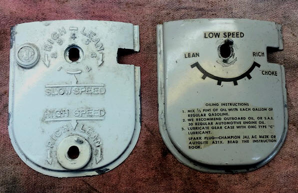
Carburetor Front Cover ; There is aluminum die cast front cover plate on the Johnsons which is held in place against the side skirts, utilizing a 3/16" lip, and then a coil spring over the idle screw and against the front of this plate. The Evinrude front plate was totally different and part of the sideplates.
This plate seems to be missing on numerous motors. My guess is that if you were working on it and needed to do any carb adjustments it would be hard to do if that plate was in place. Then after you got it tuned up and running, it was a pain to then replace the sideplate/skirts AND this front plate and still maintain the low speed adjustment needle setting.
Here that needle is designed so that the knobs can be adjusted to match the idle speeds. This locking the knob onto the needle shaft is accomplished by having the outer portion of the needle split part way back, knurled and threaded inside, using a #6x32 x 1/2" long flat head screw, where the underside taper wedges the outer tends of the needle to lock it to the shaft. On many of these old carbs the knurling has gotten worn down making for it hard to lock the knob in place, (ESPECIALLY after the sideplates and front panel has been reinstalled). There is a stop nub on each to limit the rotation to about 270 degrees. BTY, if that #6 screw gets lost or damaged, the one off a normal light switch cover will work just fine.
In the photo below, you see the differences in the carburetor front covers between the early adjustable high speed main-jet on the left (JW10) and the later that had a fixed main-jet cover on the right (JW19A)
| Here you see the differences between the Johnson carb front covers |
 |
| Here you see an 1967 Evinrude control panel which is made up of the RH and LH sides of the lower side panels |
 |
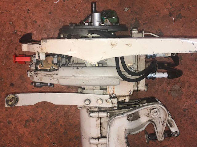
Carburetor Breather ; There is a cylindrical air breather that connects to the front of the carburetor (by 2 #10-24 screws) and lays along the LH side of the block just below the fuel tank, using one screw #10-24 at the rear, all with star type lock washers under the heads. This breather has to be removed first to be able to get to the LH carb nut.
These motors originally came with a
"bug screen" which was bolted between the carb and this breather as seen
in the LH photo below. On the right, the JW10 and JW19 both show one of the stainless
screens in their illustrated parts list, however not on the 67s. But my 67 Evinrude had the rubber one
on the far right.
The JW10 was missing it's. Some say they need to be installed for
the motor to run right? Why is it there to start with?
Further investigation, this rubber one has a great resemblance to the gasket in
the later fuel pump cover gasket. BINGO that apparently is what this one
is, why a previous "MECHANIC" would do this is anyone's guess. And
when I acquired this motor, it was a non-runner, so I will never know it if even
ran using this modification. So, remember just because a part is on
your 60-70 year old motor does not mean it was there originally.
| Here you see the carb breather on a 64 Johnson | Here you see the carb "bug screens" SEE ABOVE |
 |
 |
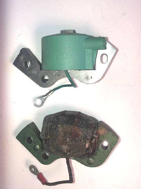
Magneto ; Upon pulling the flywheel of the JW19A for the magneto inspection, what I saw did not give me that really warm and fuzzy feeling. Both of the coils insulation was badly cranked, and to the point of chunks about to fall off. This was also the situation on the Evinrude, however the JW10 apparently had replacement coils, condensers and points.
To remove the timing plate assembly, remove the four Phillips head screws. There are two low down almost buried next to the points, these will come out. The other two have larger heads and located on top of the coil unit, these are dual threaded, meaning they will need to be unscrewed, then picked up and unscrewed more. The timing plate assembly can then be removed up and off the base plate unit.
Condition of the coils on this motor was VERY questionable, so were replaced. However after they were off, the thought was to test them to see just how bad they could be on the outside, but yet be operational. In removing top coil, the condition was worse on it's underneath side AND the boss where the spark plug wire protruded just fell off along with some closely associated insulation. The bottom coil insulation was worse and in getting it loose, it also broke off the spark plug wire.
I ordered a pair of aftermarket coils, but in their installation there was a slight issue. The new ones spark plug wire connection was built into a protruding boss on the bottom of the coil with a small screw which was inside a recess in this boss. The wire is attached by threading the wire core into the screw (no soldering). The hole in the boss that the spark plug wire goes into was a bit small for all the existing insulation to go into, so slight trimming was required. BUT, then when trying to bolt the coil down onto the timing plate, this coil boss protruded too far and too high to fit without using my Dremel tool to relieve part of the timing plate where the spark plug wire exits out the bottom.
And as a preventative, I also sealed the joint between the coil and the spark plug wires.
In installing the coils, there is a a location ring tool that should be used.
This tool #0317001 is to set the air gap between the coil heels and the flywheel
magnets, it works for motors from 3-40hp 1951-1976 and many beyond that.
If that tool is not available, look closely at the bosses cast into the timing
plate where the coils are screwed onto. On the outer edges of these bosses
are machined circular surfaces. Here, you need to align the outer heels of
the coils (so there is no mismatch) with these machined surfaces. There
SHOULD be enough looseness in the retainer screw holes for the needed alignment.
However you may need to convince the coil heel into position with a love tap from a hammer.
The holes in the aftermarket bottom coil did not totally
matched to the timing plate threaded screw holes, not allowing the coil to be
moved inward enough and it drug on the flywheel. The only thing to do was
file both the heel and center of the coil for clearance. This was done
with the help of layout die (or black felt marker) being used on both the coil
protrusions and the flywheel. Bolt it down and try to rotate it, unbolt
and file off where the metal was rubbing.
The points were pretty pitted on this motor, but I just cleaned them up with a point file and set them at.020". New points sets are $20 each plus shipping. That is about $46 per motor, even if they are badly pitted and are filed with a point file (cost about $8) because the points are so hard, you will ruin a file after about 3 or 4 sets of filing, but still a good value if you can save them.
The condensers looked good, but not tested, however in the dry testing, it only had spark on the top cylinder, all tests indicated the condenser was bad.
| Here you see two not so good looking coils with badly cracked insulation | Here you see both the old and new coils |
 |
 |
One thing
that you might do after you re-install the timing plate, is to double check IT'S
rotation from Slow to Fast, as the screws under this timing plate are location
specific. Meaning one may a flat head and needs to be in the proper
location for it's head clearance to the timing plate in order to operate, or you
may have put a flat washer under it's head.
It may be best to check this BEFORE you do all the rest of the installation,
otherwise you will be in for a surprise when the throttle lever will not rotate
it's full rotation.
The magneto on the JW10 appears to have been completely rebuilt. But the one on the Evinrude 3022 again had very bad coils.
Power Head ;
Here, with all the work I have done on this motor, (JW19A) I might as well
pull the head and look at the condition of the cylinder walls and replace the
head gasket, the first thing I noticed was some hardened calcium type
deposits in the water jacket of both the head and block, and the head gasket
also had some blockage also. The cylinder walls looked great, but the tops
of the pistons had a lot of carbon on them.
While waiting for the head gasket to come in, I tipped the motor
up as horizontal as possible, rotated the flywheel to where both pistons were
above the inlet/exhaust ports and poured enough Sea-Foam in the cylinders to
cover the top of the pistons. The bottom one cylinder held this liquid pretty well,
while the top one slowly leaked down a bit and then both pretty well stopped. My thought here, what better way now
to decarb this engine, reaching right at the source for the pistons and the
rings? As a final measure, I lightly honed the cylinder walls by pushing
each piston as far down as possible.
These motors are pretty bulletproof (literally) if any care has been taken. One interesting thing here is that this motor does not utilize either a crankshaft seal top or bottom. However as I work on more of them, I find a neoprene O-Ring on the crankshaft above the oil slinger ring. This was on a1967, but not shown in the parts list.
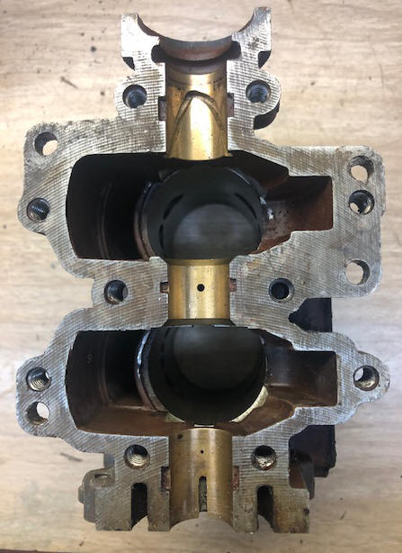
Here the main bearings are a cast in bronze, but both are substantial in length. They both have oil retainer/lubrication grooves, probably designed for the richer fuel/oil mix serving as a seal. And on the upper part of the crankshaft there is an oil slinger ring (as seen in the RH photo below) directly above the upper bronze bearing.
The blocks on this series appear to be different for the early (1952 to 1963) to the late style (1964 to 1967). Not sure about the 1968 as it may well be different also. These blocks look pretty much alike and maybe so, but the lower section that adapts to the clamping bracket/midsection is different. The later block uses an adapter plate between it and the midsection, where the earlier version this adapter was part of the midsection.
| Here you see the rear 1/2 of the block with all the bronze bearings, also were the rod bearings | Here you see the crankshaft |
 |
 |
The crankshaft also appears different
between the early and late motors. Part numbers are different, and in
observing them closely, the later ones are heavier at the inside corners of the
juncture leading to the connecting rod bearing journals. My guess is this
is counter weight to balance the heavier flywheel that now has to match the new
starter unit. This could also explain why the rings were changed to
narrower, for the same reason - to gain a few ounces in balancing the motor's
parts.
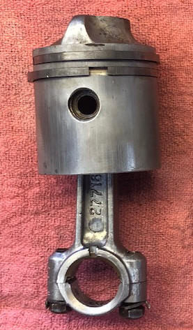
In the photo below is a sneak peek at the pistons.
The connecting rods AND the caps have a slight ridge close to one bolt hole.
These ridges are to identify the relationship / orientation of the cap to the
rod, as they were machined as a set. The bearings are again bronze cast
into the aluminum connecting rod, necessitating a richer fuel/oil mix, as
compared to if they were needle roller bearings.
| Here you see a pair of JW10 used pistons | Here in the upper part of this view, you see the small rod cap alignment ridges |
 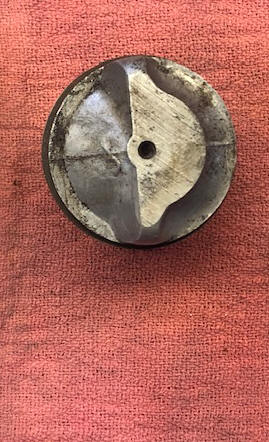 |
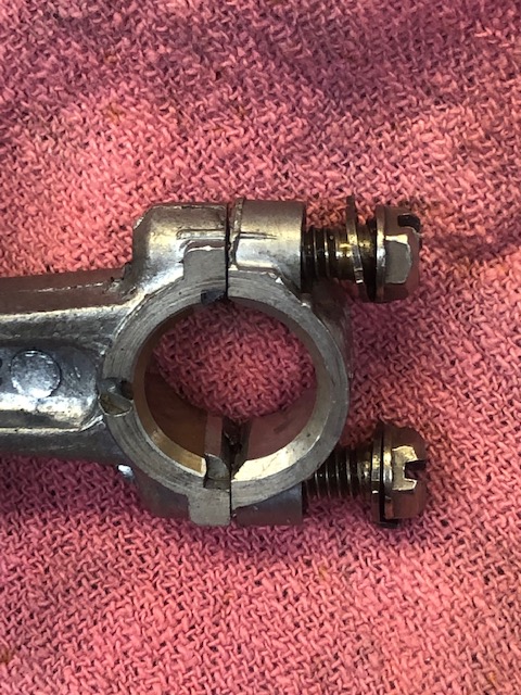 |
The factory changed the piston rings over
time also. The older (1952 -1963) had wider rings (.092") while 1964 and
later went to (.061"). When installing or re-installing the new thinner
rings, BE VERY CAREFUL as they can be broken easily, (especially when you are
trying to expand them to insert the piston into the cylinder).
In the photo below you can see scoring on the piston skirts.
This corresponds to the intake ports, WHY? Normally any scoring would be
on the exhaust side because of possible carbon build up, where intake ports
would normally not have that. The cylinder walls were not scored. However
this 1967 had evidence that it had seen wrenches before, and it had a different
color head on it. So maybe at some time in the past the pistons may have
been installed backwards??
I tore this powerhead down because of a lower
compression (about 20#) on number one cylinder. I suspected it may have
had the rings seized in the piston. No, they were fine, and the tops of
the pistons were fairly clean, as if the motor and not been ran much after the
work had been done. So, clean everything, band-sand the pistons to help
remove some of the scoring, and hone
the cylinder walls, then reassemble it right.
In the cleaning/reassembly I find that this motor has
been bored and .020" oversize pistons installed. I wish it could talk to
me. Are these pistons out of a different motor?
More tearing into it, I found that 2 of the rings were not totally in contact with the cylinder walls (like the rings were slightly egg shaped, (or possibly standard size instead of the .020 " oversize) ?? OK, I honed the cylinder walls slightly just to break the glaze. Then I bead blasted the rings with glass beads, to also break the glaze on them. Then on re-installation, I made sure that those faulty rings were not in the top grooves.
After
reassembly this crankshaft seemed to be dragging, but probably more
from the new hones and bead blasted rings. So to do a mini break-in,
I used a 1/2" chucked battery operated drill motor to rotate this motor for a
few minutes, instead of pulling my arm off trying to start it.
|
Here you see used pistons off both
the newer & older motors showing the different style rings |
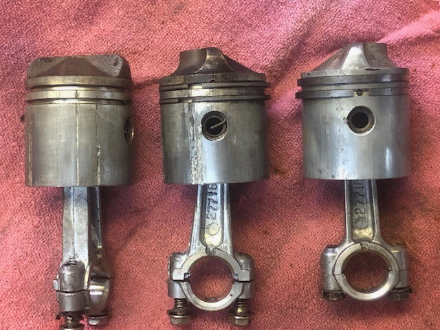 |
In the photo below you see an illustration of the orientation of the piston, with the
sloped side toward the exhaust. Here the top of the piston, on the intake
side (spark plug) is designed so the fuel is directed IN and UP, more like being
trapped on that side at the end of the intake stroke instead of allowing it to
be blown across the top of the piston and loosing some of the fuel mix out the
exhaust.
| Here you see the piston orientation |
|
|
One
thing
on these motors, if you remove the head, it may be a good idea to
mark the TOP. The spark plug holes are slightly offset to one side
(the RIGHT).
On this model the spark plug locations are designed to match the contour of the
tops of the pistons. The head needs to match the top protrusions of the
pistons allowing for the combustion (spark plug side) like in the photo above
which would be the RH side here. This head can be installed upside down
and will run, but will not run efficiently, as it can not utilize the fuel from
the intake ports as designed. And the top corners of the piston ridge may
hit the head.
The top (upper area) of the head has a slight 1/8" X 3/8" protrusion slightly positioned to the left. The head gasket also has a mating protrusion, this is an indicator which needs to be in the UP position.
On this JW10, it appeared to have been made up from possibly three motors. The paint, was from two different motors, and I have replaced the missing starter. The clamp bracket, gas tank and side skirt was a greenish gray where the powerhead, mid section and lower unit was a dark forest green, both not being original colors. And I picked up the starter unit separately from am AOMC member. The rear section of the lower exhaust extension was broken off, and when trying to remove the head, one bolt had already been broken off, and I twisted off four of the other six. The head was then seized onto what was left of the head bolts that were inside the head bolt holes.
| Here you see the spark plugs offset slightly to the right |
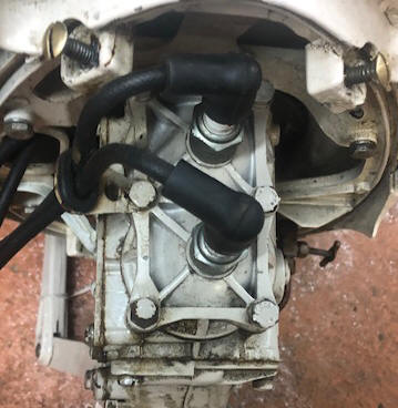 |
Trying to soak these broken bolts proved fruitless, so maybe I could remove the block and crankshaft, then by using the connecting rod, drive the head off. WRONG, I just broke off the threaded part of one connecting rod. Where to find another rod? OK, I have another 3hp Evinrude 3012 that has broken side shirts, and I did not have any thoughts about restoring it, but to use only for parts. Now becomes it's chance to contribute.
Maybe, while
this deep into this project, lets look at the cylinder walls of the Evinrude
block. Here again in
trying to remove this head, but this time only one bolt head twisted off.
More soaking with penetrating oil, but to no avail and it broke off in the
block. Well, one is a lot better to drill out than four.
In the series of photos below, you will see the sequence that I used for removing this seized/broken off 1/4"X20 head bolt drilled out using a .170" dia. drill (just enough undersize to not damage the bulk of the threads). By mounting it in a rigid vise and aligning the center drill, very slightly off center. CAUTION, this may be possible if drilling by hand, BUT, take my word for it you will usually not drill neat and clean as shown here. The reason for slightly off center is that allows me to, by using a Dremel tool high speed drill motor, and an 1/8" carbide cutter, I then can cut through the thicker side of this hole, allowing me to collapse 1/2 of the threads as seen in the RH photo below.
| Here you see the block mounted in a 6" milling machine vise & a center cutting bit aligned over the broken bolt. | Here you see the slightly undersized hole drilled & 1/2 of the bolt threads loose IN the hole after Dremel tool cutting through one side |
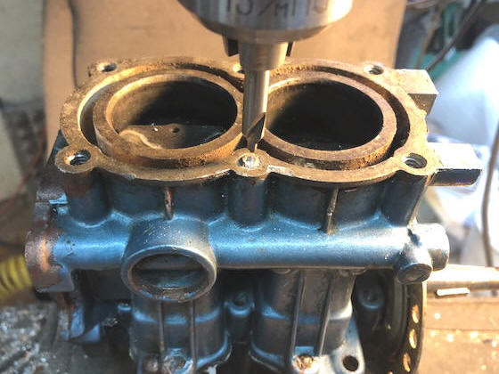 |
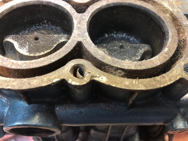 |
In the LH photo below, you see what is left after the broken sections were removed. Here I probably still have 70% of the original threads, Now I use JB Weld epoxy to fill the gap, by first, cleaning this hole with acetone, smearing Vaseline (which will act as a release agent) on a NEW 1/4" bolt threads, (slightly warming it so there is a thin coating all over the threads, and while warm shake off the excess). Then smear some of this epoxy in the hole's void, along with a thin amount on the bolt's threads. It doesn't hurt to SLIGHTLY overfill so that when you thread the bolt in deep enough (nearly bottoming out), it will force some epoxy back up into this void by hydraulic action, leaving no air bubbles).
Using regular hardening "original" JB Weld (not the 5 minute type) let this set for just long enough to have it set up about 70 to 80% (6 hours works for me). Now slowly unscrew the bolt about one turn, just enough to break any bond that may have happened. Let it set overnight and then unscrew the bolt. Now, I like to (just for jollies) run a tap down into the threads just as a precautionary measure.
| Here you see the broken bolt removed from the block, leaving about 70% of the original threads | Here you see the pieces of the drilled out bolt & the chips from the Dremel tool usage |
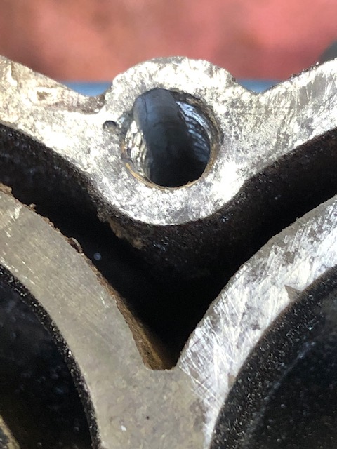 |
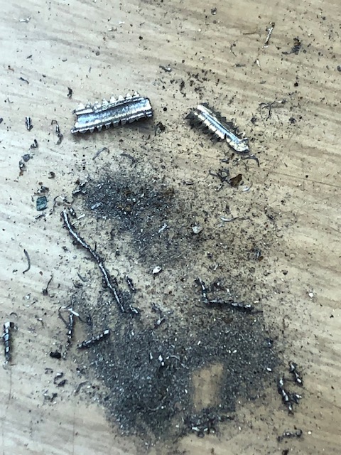 |
Then when done, I trued up (leveled both the block and head surfaces). This was done using a sheet of #80 grit sandpaper, laying on a solid flat table surface, and forcing the metal over the top of the grit, removing any bumps or warpage.
Tell Tail Water Discharge : There is no indicator of overboard water on motors made after 1963 when the water pump is operating properly. Prior to that there was a misting (of sorts) on the front mid lower pivot tube (back pressure relief holes). These OLD 3hp motors have the water outlet incorporated into the idle relief port on the front of the exhaust housing (out of each side of this bracket) and it is covered by a small plate. It’s hard to see the water coming out as it can be a spray or a dribble. The later motors (1964) and on have a few small holes in the rear of the midsection above the cavitation plate that is a bit easier to see the blubbering. I contemplated installing a overboard pee tube, but since these motors have no thermostat, it was questionable if that would disrupt the cooling system.
Thermostat : As mentioned above, these motors were designed without a thermostat.
Shroud / Sideplate / Shirts ; These Johnson motors use a single formed aluminum sheet stamped wrap around shroud that covers the lower part of the motor from the fuel tank down. It has 2 screws on the front and 2 more on the rear. Note that there is a slot on the RH front side that accommodates the fuel shut off valve, this valve has to be positioned to match the shroud slot for reassembly.
NOTE, if this shroud for the Johnson has become bent, dented, misshaped, it
needs to be lovingly reshaped as best can be to allow for installation. The Evindrude's being a
two piece aluminum casting would not be susceptible to this.
Front Grip & Tiller Handle : For the early Johnsons there was no front carrying handle (but the gas tank base was copied from the TN models), however it had a handle on the bottom of the rear cowling. Later there was a 2 piece front handle that is screwed onto each side of the skirt, this handle being split on the LH side with a screw there needed for disassembly. Evinrude's carrying handle was made as 1/2 part of each of the lower shrouds.
The tiller handle
bracket is a simple extension hinged steel strap bolted to the rear of the block and under the skirt.
The rubber tiller handle was slid onto the top of the front pivot arm.
Clamp / Tilt Bracket
;
These motors have 2 different styles of transom
bracket clamps. The early used two up until 1963, while the later versions have 1 screw handle,
both
using the newer folding
type handle. At this change, they also changed the mounting of the
upper midsection to the powerhead.
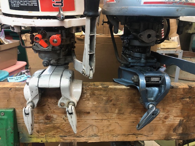
In the photo below, the 1963 Johnson on the left, with a 1966
Evinrude on the right.
| Here you see the difference between the pre 64 and the post 64 clamp brackets |
 |
Again in 1964, the swivel housing was changed to
rubber shock absorbing mounts both top and bottom, which also gave the motor a
bit more of a quieter and less vibration motor. Also in the front of this housing was
incorporated a grease fitting. I guess someone was thinking.
At the lower part of the outside bracket, is what the factory calls "thrust socket adjustment".
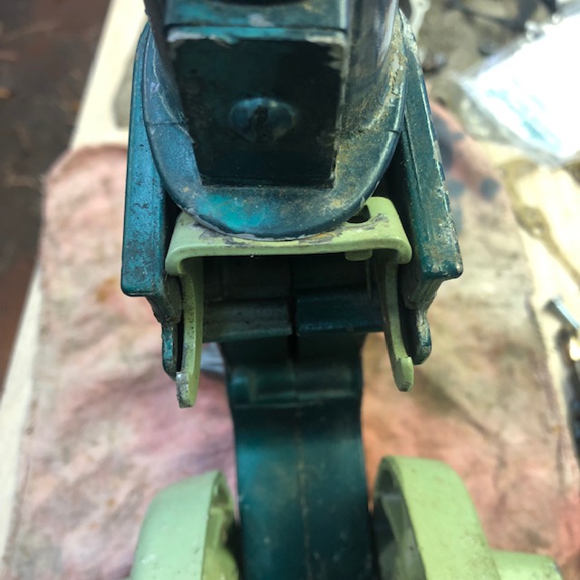
Reverse Lock : Also in the lower part of is bracket unit described above, is incorporated a reverse anti kick up devise when the motor is rotated starting at about 90 degrees. There is a protrusion on the midsection front outer part that deactivates the spring loaded reverse anti kick up lock system during normal forward operation. When rotating the motor more than about 90 degrees, the absence of this protrusion activates the spring operated lock.
|
Here the Reverse Anti Kickup devise deactivated in the forward position |
 |
Tilt Lock
:
These
motors have no up tilt lock position, other than tightening of the hinge pivot
bolt
of the clamping bracket. There are Nylon friction washers between the
bracket arms and the midsection pivot area. This bolt on the RH side where the nut is
located, has a short length STRONG spring under the nut, so tension can be
obtained.
Lower Unit ;
This motor does not have a sifting system, but is direct drive and
for reverse, it has 360 degree steering. These could be
had in either the Standard or Weedless versions. The
standard would have been the 90 degree angle from the exhaust
housing leg, while the Weedless was at a downward angle with the
leading edge made as a straight line. The water pump is
mounted on top of the lower unit (gearbox) using 2 screws from the
top, and is the same for either version.
In removing the lower unit, there are (4) 3/8" headed 1/4" X 3/4" stainless steel bolts that come in from the bottom, (gearbox side). Remove them and the whole lower unit including the driveshaft can be withdrawn from the crankshaft splines and out of the exhaust housing.
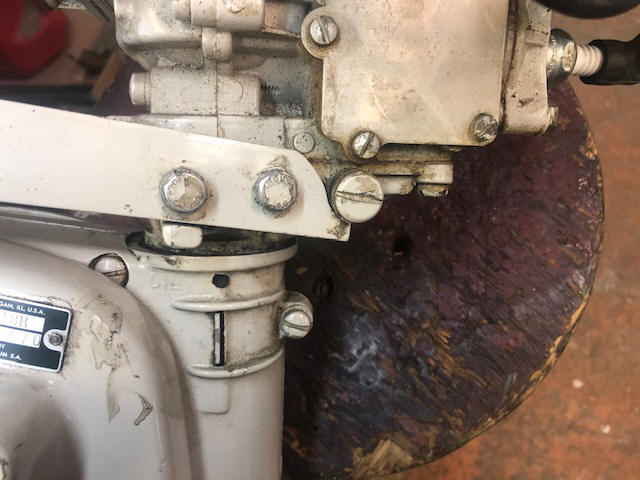
Flush Plug ; There is a "Water Flush" plug located on the rear lower part of the motor adapter to midsection, near where the two tiller handle base screws are attached. There is cast in the base "Water Flush" lettering and just ahead of this writing is a 5/8" dia. slotted plug. This provision was discontinued when the single clamp bracket/midsection system was brought out in 1964, probably because that plug was the location in the newer unit that in the new adapter plate is here one of the four attachment bolts is located.
| Here the Water Flush plug, the large screw head behind the tiller handle base screws on a JW19 |
 |
Water Tube & Changes ; The water tube is 1/4" OD copper tubing. Here are three different water tube outlet types from the water pump to the block. (1) From 1952 to 1963. (2) From 1964 to 1967. And (3) from late 1967 to 1968. The differences are how and where the tube attaches to the lower part of the powerhead adapter and to the block.
For the early motors, the tube is attached in the LH inside of the midsection/block adapter and it will not come loose from there when you remove the gearbox. It is attached here inside where the water Flush Plug is located. In reassembling the lower unit onto the midsection leg, it is easy to visually align the lower end of this tube (as it sticks down far enough to see with the lower unit partly aligned) into the water pump grommet as the lower unit is slid up meshing the driveshaft splines into the crankshaft.
Water Pump Impeller Replace ; On top of the water pump housing, there are 2 slotted head screws that when removed, the housing can be lifted up off the gearbox. With the water pump off, DO NOT lift the unit by the drive shaft. Otherwise you will disengage the drive gear in the gearbox and will need to disassemble it to rein stall that gear. It is basically held in vertical position by the impeller AND it's key when the water pump housing is screwed in place.
To remove the housing and impeller up off the top of the driveshaft, you will first need to remove the small Neoprene O-Ring that is on the upper end of the driveshaft, just under the splines. This O-Ring is there to keep water from creeping up and into the splines, rusting it to the point that at a later date another mechanic may have problems withdrawing it from the crankshaft spines.
Slide the housing and impeller up and off the driveshaft. IMMEDIATLEY remove the impeller key from the driveshaft, the earlier versions simply used a1/8" X 5/16" stainless steel pin. The later keys are made like a Tee, using the bottom as a small rounded stud that is inserted into a round hole in the driveshaft. The top (exposed part) is square, mating into the impeller slot. Remove this key and place it in a secure location, as they have been known to play the hide and seek game.
| Here the water pump impeller keys |
 |
The JW19A pump housing was good enough to be reused, however the JW10 had pitting around the inner periphery. I looked around for a replacement, only to find they were obsolete, and a few surviving Old New Stock, but at a price of from $70 to $144 just for this housing, with a few complete kits listing for a mere $169.99, as of 4-2022. And the new outlet grommet itself sells for only $15.95. I am beginning to understand why they have a higher monetary value by stripping these motors down and selling the parts separately.
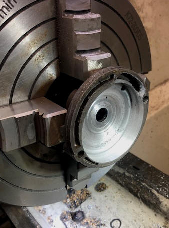
My only option here was (as I have done before) was to mount it in my metal lathe, and since the outer part of this housing is not concentric with the center shaft area, use it in a 4 jaw chuck. I had to dial it in by hand (trial and error for an hour) until I finally got it to within .004" of being true (FYI, a sheet of newspaper is about .003"). I then machined out about .010" to .012" in order to clean up the pitting. I could not get the inner face flat enough in the chuck to re-surface it also, and did not really want to deepen that area very much anyway. I had to compromise as to not go too far and ruin what I had. Then by using 300 grit emery cloth as it was spinning to smooth out the cut, it came out acceptable as compared to what was originally there upon my disassembly.
| Here a JW water pump housing being dialed in, notice the corrosion there |
 |
In the photos below, on the LH photo, the housing about to be bored out to clean up corrosion. On the RH photo, while still in the lathe, you can see the improvement. The slight circular scoring in the center should be of little consequences as this is at the hub area and not out on the vanes.
| Here the JW water pump housing before machining | Here the JW water pump housing after machining |
 |
 |
Sierra number
18-3001 is the water pump impeller ($9.98 on eBay).
| Here the re-machined water pump housing and new impeller installed, with the old one shown at the side |
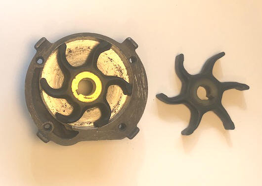 |
In the photo below, the used impeller may still have some life left, but at the price of new ones, and not knowing what was inside at the time of my recent purchase, I usually just replace it. In my thoughts, these impellers having longer vanes (like this one) seem to have a better lifespan, as compared to the ones with shorter vanes. Except when the pot metal housing is pitted, then the vanes get worn on their leading tips.
| Here you see the new and old water pump impellers |
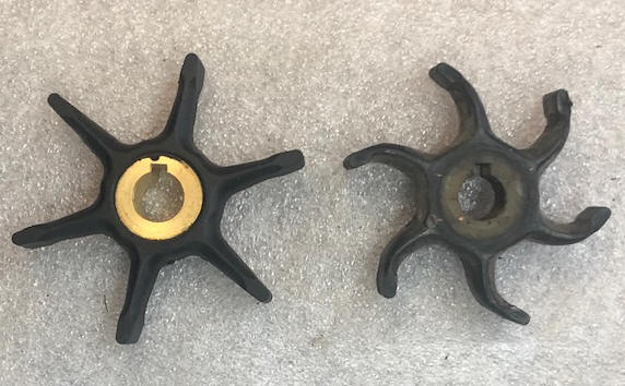 |
Disassemble Gearbox ; Here, the reason is to reinstall the lower driveshaft spline into it's drive gear that may have been disengaged during the impeller replacement (IF the motor is a weedless drive). The early motors (52-54) have a brass acorn nut to hold the prop on. On the later motors the prop has a rubber cap that has to be pried off, remove the nut's cotter pin and nut, the rubber cap can then be pulled off the prop shaft. Remove the shear pin.
Drain the gear oil.
Go ahead and pull the driveshaft out of the gearbox, now that you have already let it move enough to disengage the drive gear inside. Plug the driveshaft hole using a cork plug (1/2" dia. on the top), to prevent any remaining gear oil from leaking out if/when you inadvertently tip it upside down and/OR have not drained it yet.
There are two slotted head screws, (top and bottom) holding the gear housing in place. Remove them, then you need to tap one or both screw bosses (ears) sideways enough to by using a small hammer or about a 3/8" punch to tap the gear housing rearward. This housing is a slide fit into the main housing and uses a large Neoprene O-Ring as a seal around the gear housing. HOWEVER, it will not come out without removing the lower oil fill plug (which protrudes just enough inside to block the removal). Tap each of these "ears" alternating so that you move the gear housing enough to remove it straight rearward from lower unit housing.
The gear housing will come out as a unit, leaving in the drive gear and the prop shaft thrust bearing inside. The drive gear will be captivated inside the housing by the thrust bearing. If you need to remove the thrust bearing, you will have to make a puller as shown in the photo below. You will need to tap the existing center hole out to 1/4" X 20 TPI, then using a piece of 1/4" all-thread, cut it 10" long, bend a 90 degree handle 3" from one end. NOTE - the long leg needs to be at least 6 1/2" long as there cavity in front of this bearing is deep. Here you just keep threading it in until this Nylon bearing is pushed out. You can also use this puller to reinstall the bearing , but for this you only need it threaded in about the thickness of the the bearing.
| Here you see my homemade thrust bearing puller |
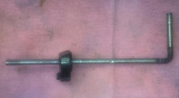 |
With it now apart, you might as
well drain and flush the
old oil. If it was leaking, you will need to replace both the
lower drive shaft seal (under the water pump) and the prop shaft seal (both the
same seal, 7/16" ID X 7/8" OD and 5/16" wide). OMC # 0327031 or Sierra 18-2035 @ $9.95. And
while there you might as well also replace the gear housing
O-Ring (which appears to be 1 7/8" OD X 1/8" thick) OMC # 0301917 @ $1.22, all still available as of 11-26-2022.
However you will probably not find this in even a well stocked
hardware store as this O-Ring is an odd OD size.
The Yachtwin uses a different more Heavy Duty 90 degree drive lower unit. This one does not have the above mentioned removable Nylon bearing plate.
| Here the Yachtwin gearbox |
Reassemble Lightwin Gearbox ; Here, if you do not want to disassemble the gearbox AND have allowed the driveshaft to move up and out of mesh with the inner drive gear, there is hope. Using a flashlight, look down inside the driveshaft seal hole, and with a long screwdriver, reach in and try to move this inner gear to where it's hole/splibnes are aligned with the hole in the gearbox. This gear is captivated in by the thrust bearing, that when not engaged with the driveshaft will not fall into the main oil housing. Now try again to slide the driveshaft down and into it's mating spline, by slightly rotating it as you push down.
If you have the gearbox all apart, to reinstall the drive gear, it may be best to tip it over so the driveshaft is now going in from the bottom, slide it in just enough so you can see the end. Then using a long screwdriver (unless you have long fingers) re-position the drive gear so that you can now align the gear onto the end of the driveshaft. Push the shaft all the way in so you can now see it slightly protruding out of the gear. Hold the driveshaft in and rotate it in the upward position.
Locate the impeller key. Locate the bottom stainless steel impeller wear plate and install it with the worn side UP. Lubricate the upper part of the water pump housing with a liquid soap, (for me, Lemon Joy works). Position the impeller in the pump housing, by rotating it in a RH manner as if it was on the motor and motor being rotated as if you were cranking it to start, (looking from the top of the housing). With all the impeller vanes inside the housing AND all the vanes pointing in the same direction slide it onto the upper part of the driveshaft (aligning it so the shaft engages the impeller. Slide this unit down and into just above the home position. Place the key in the shaft hole and position it so the flats are parallel with the shaft. Make note of where the impeller key slot is, aligning it with the key and slide the impeller and housing unit down, rotate as needed for alignment of the 2 screws, and tighten them down. Now your driveshaft is secured by being keyed to the encapsulated impeller. Replace the upper driveshaft O-Ring at the lower section of the splines and using a finger full of trailer axle grease smear some on these splines.
You can now reassemble the
prop-shaft housing assembly (driven gear, bearings and seals).
Smear a slight amount of grease on the inside of the gearbox opening
(to lube the O-Ring). Slide in and rotate the shaft while
doing so to allow for smooth meshing of the gears. Install the
2 housing screws and you are ready, other than replacing the gear
oil.
Replace Lower Unit ; You now can reassemble the lower unit and driveshaft assembly back into the exhaust housing. This motor requires a little different approach here. Instead of aligning the water tube first, for me at least (after 6 or 8 tries) I found that it (the tube) is long enough to engage the driveshaft splines first and then very carefully using along skinny screwdriver reaching in the gap of the exhaust housing and gearbox to align this tube into the water pump housing outlet. The water tube is small (1/4") and easily bent interfering with reassembly, but it is also very easy to re-bend for less misalignment on reassembly. When you think you have it, there is just enough room, by using a flashlight to visually see whether it is engaged in the pump outlet, before you tighten it down. One note here FYI -- For me it worked a lot better to tip the motor upside down (with the flywheel resting on the floor) for this part of the installation.
Propeller ; There is a bit of confusion here, (for me at least) on the propellers, as the first three years the part numbers and illustration shows a 3 blade prop. All later ones are 2 blade, and the folding motors show a 3 blade again.
Since these motors have no shock absorber in the drive system, there is a rubber prop clutch (of sorts) which is a ribbed rubber ring (#300565) between the inner prop hub and the prop itself as seen in the photo below.
This would not normally not need service, however occasionally it may be a good idea to disassemble, clean and reassemble it, just to insure that it was still operational when you may need it. In reassembling, you want to spray some Silicone lubricant on the inner ribs and hub ridges. Also be sure to lube the prop shaft lightly (using boat trailer axle bearing grease) to protect it from seizure for the next time you (or the next guy) need to get the prop off.
This rubber clutch ring #0315471 is still available at $32.99.
The early versions of these gearboxes used a stainless steel acorn prop nut (7/16" NF). The later versions had the same threads but a larger thinner nut that has a slot in the middle for bending the cotter pin in to, BUT on one side it also has a smaller dia. turned down section, this has to be positioned inward to retain the rubber rear nose cap, which snaps into the grove created by this recess when installed. It also has cotter pin holes on every flat, for better tightening and cotter pin insertion.
It is also a good idea to replace the prop nut cotter pin each time, otherwise you run the risk of this pin (if being reused numerous times) to break, allowing the nut to unscrew and the loss of a prop. At the age of these motors, finding a replacement may be a real issue.
| Prop components of the later version with the plastic washer in the prop |
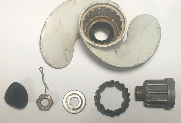 |
Folding Motors ; I cannot identify exactly when the folding versions of either of these motors (Evinrude or Johnson), first came into being as it was left out of the chart that I copied above. However the bulk seem to be after 1963 when the clamping bracket went to a single clamp handle. However, I have seen a photo of a 1959 and verified as having the older clamp bracket.
The whole powerhead was the same, just the water tube, lower part of the midsection/folding unit were changed. The gearbox itself stayed the same, just the driveshaft attachment was different as seen in the photo below.
This motor, I made up from two motors. I managed to purchase the 1966 complete lower half off eBay and I already had a 1967 Evinrude that I had picked up for parts. The only modification I had to make was to shorten the water tube from the block to the juncture of the folding hinge section. Here I found that this tube needed to be just shy of 12 1/8" from the brass compression nut head to the bottom of the tube.
The water pump stayed the same, but the outlet tube are made in two pieces to match
the folding unit.
The upper water tube stops in a rubber grommet at the juncture of the upper and
lower housing. This grommet then becomes a seal when the two units are
bolted together.
In the photos below, you can see the difference between the
Yachtwin and the Lightwin lower units. This Yachtwin has just been
rebuilt and primer painted, as it ultimately be the same color as the Lightwin..
| Here you see the Yachtwin lower unit, for a folding motor | Here you see the lower unit (gearbox) for a Lightwin folding motor |
|
|
 |
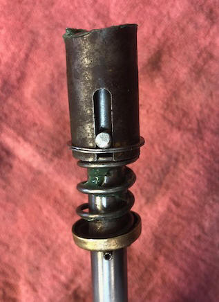
In the photo below you can see the spring loaded coupler for the folding model lower shaft coupler. This has a slight dual taper on the upper end AND a slot below that connects this lower driveshaft to the cross pin in the bottom end of the upper driveshaft. Here it might be wise to position this snap ring as shown below it's retaining cross drive pin. This snap ring is essentially a THIN double lock washer which snaps into a VERY SHALLOW retainer groove.
| Here is the folding coupler, showing the snap ring that retains it in place. | |
 |
Issues With This JW19A Motor ;
When I answered the FaceBook Messenger add for
this motor that was for sale, after looking at one of the photos he
had posted, I asked a question. "How much damage did the bullet into the gas tank
cause?" It took him a bit to respond, but he indicated
the motor still pulled over OK using the starter rope.
When I got there to look at it, I requested that he pull the starter unit
off so I could see if it had damaged the flywheel, magneto or the
starter. When he took the starter off, he said that he
had already done that and a piece of brass fell out, but he could not
figure out where it belonged. It turns out that the copper
that fell out was probably what was left of the bullet.
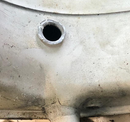
| Here an enlarged view of the bullet hole |
 |
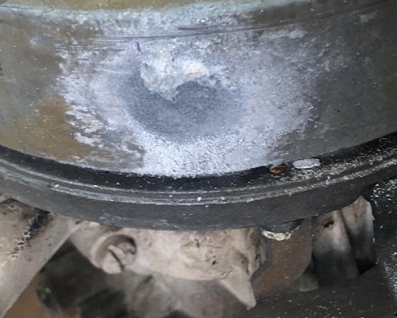
Shown below are photos od the bullet exit hole of the tank and it's impact location on the flywheel. This location was on the inner edge of one of the cast in magnets of the flywheel, which provided enough stopping power to not damage the flywheel. If it had been 3/4" higher or lower, the starter or magneto would have been damaged. Apparently the brass that the previous owner found was what was left of a 9mm bullet (based on the in hole's dia.).
| Here is a photo of the bullet's exit hole on the gas tank | Here the bullet's impact on the flywheel |
 |
 |
The story he told was the motor was in a old shop behind the other buildings that had a LARGE fir log butt cut on the outside of this wall. This stump was being used for a backstop for the 22 rifle plinking. The property belong to has parents and his father had died 3 years before, so he was getting rid of stuff for his mother. Apparently someone unbeknownst to him and at an unknown time, had tried their marksmanship (or lack of it) with a pistol and missed the whole stump.
There was still some stale gas in the tank, but it had not dried out and gotten hard yet. I plugged the bullet holes with small corks. And using a about 1 1/2 pints of Rubbing Alcohol, and a hand full of abrasive tumbling stones inside the tank. By shaking it in all directions every time I passed by for a few days, it got clean. Then when everything was dumped out, the alcohol evaporated, leaving no fumes so my welder friend had no problems aluminum welding patches over the holes.
When I finally got around to trying to start this motor, I had so much trouble that I had decided it had to have been a female motor with PMS, being cantankerous on trying to start after a rebuild. Here I had replaced both coils, filed the points considerably and readjusted them, pulled the head while I was there and cleaned the carbony pistons, and lightly honed the cylinders, where the compression was 70 and 74#. New spark plugs and complete carburetor kit along with a new water pump impeller.
It had fuel in the tank, the fuel line was clear and the shut off valve was on. I wanted to try to dry start it after this repair, so squirted starting fluid in the carb inlet throat. It would not even pop when pulling the rope. I then began using a drill motor and 11/16" socket on the flywheel nut to turn it over. Checked the spark plug jump, one was dead, replaced that condenser, which cured that issue. But still no pop. Pulled the carb to double check my assembly and while there also pulled the reed valve plate to check their operation. Replaced the carb only to find that I forgot the manifold to carb gasket, OK, tear the carb off again. After reassembly, still no pop. Finally, things were really not started to add up, after a lot of thinking, the starting fluid was not a spray, but more of a mist. I began to wonder, this can of starting fluid was a different make than I usually use, so I finally looked at the name on the can, "Silicone Spray". I had grabbed the wrong can. One squirt with the right stuff and it fired right off. I had spent way more time double and triple checking my repairs, but found my stupidity was the culprit.
Issues With This JW10 Motor ; When I picked this motor up at an estate sale , it was a mismatched repaint job, indicating parts off two motors, and it was missing the starter assembly. I had picked up a starter unit from a AOMCI member in a trade, (that miraculously was the right limited production model, and fit), but was missing one of the three engagement pawls. I delved into this motor's repairs while waiting for parts on another motor. This magneto was very good condition, indicative that it had all new electrical parts. The lower unit's rear exhaust housing extension was broken off and missing. But as mentioned above, I had a seized head (4 broken off bolts) and in trying to remove it, I broke a connecting rod. Therefore I decided to use a Evinrude 3022 as a donor motor, which lots of parts would interchange.
To save the integrity of the JW10, why not use the Evinrude powerhead, midsection and lower unit, swapping the clamp bracket (with the model number on it), gas tank mounting bracket and gas tank, rebuilt carburetor, magneto and lower skirt? However this is going to require a complete new paint job (unless I wanted a calico motor) and going this far, new decals in the future also.
However in getting deeper I found that the upper midsection to block section of the Evinrude had a hole in the rear about the size of my little pinky, right where the exhaust would blow outside the housing instead of down and out. So back to the midsection of the JW10 back onto itself.
The hidden bugaboo popped up when I started to change gearbox oil in the new motor (using the Evinrude lower unit). When removing the lower fill plug, all I got out was WATER. OK, time to also swap the gear housing and seals from the old JW10.
Compression on the Evinrude was 73# on top with 75# on the bottom cylinder.
Even though this compression was good,
I wanted to pull the head, looking for debris in the water jacket. In trying to remove the head, I broke off one bolt
of the 6. I removed that
as per the extensive photo coverage above. While the block was off, I
lightly honed both cylinders, (just to break the glaze) down to the top of the
pistons.
The lower unit off the Evinrude was now used onto the
Johnson midsection. However as mentioned above I found fresh water in the old gear oil in preparation to
replace it, only clear water ran out. OK, pull the gear housing and check
how bad it is inside. Looking back, when I looked at this motor at an estate sale on
Saturday, they were somewhat taken aback from all the questions I had asked, and
I did more looking, buying some old tools, but saw them drag out a garbage can
as I was leaving. Apparently they filled it with water and tried to
start it (hoping to get nearer their asking price of $300). I had made an
offer of $75, and was there the next morning with my testing equipment, but when I
got there, they quickly recognized me and had decided to accept my offer from the day before. This
water in the gearbox had to have come in overnight from the garbage can, as there was no rust
at all inside the housing and the water was clear. However I did swap out the gears and housing unit
and new seals.
So, in the long run, this motor has the starter unit off another donor, the gas tank, carburetor, clamping brackets, midsection, side skirt of the and prop off the JW10. The Evinrude contributed the power head, lower unit. Therefore in counting parts off different motors, (as the Johnson already had parts off 2 - as the midsection was a different paint) this one now has used parts off 7 motors if you count the parts needed to compete the starter pawls (bought off eBay). Then with a NOS starter spring, along with a new replacement rubber tiller handle, that bump the total to be 9 or 10.
This one being an early motor will probably be stripped back down, repainted back to original color and with new decals.
| Here is my Calico JW10 |
 |
Issues With a 1957 Evinrude 3706 Motor
;
When I acquired this motor, compression was 64# on #1 and 80# on #2,
not anywhere equal, meaning that I was going to have to get inside
and see why. Some of the bolts had evidence of previous
wrenching, it had a Sierra head gasket and was missing the spark
plugs, so someone was trying to get it running. It also
was missing the starter unit, the owner promised he would find this
and call me, GUESS WHAT, don't believe all you are told at the
time of the sale.
Above in this article, I describe the issues
encountered with the pistons on this motor.
On this motor, I had to soak the carburetor overnight
in carb cleaner and install a new carb kit. Also the
water pump housing was slightly pitted, so another setup on the
lathe four jaw chuck and slightly bore it out a few thousandths, as
these housing are not available anymore, I then replaced the impeller.
Carburetor Front Cover, Making New Ones ; These covers are long obsolete and often missing. OK, I decided to try my hand at making new ones. From what I have found there are three different ones. I have two as samples. My plan is to copy the front (the exposed part) by taking a Bondo body putty mold, then by using it, make a fiberglass reinforced resin cover, but slightly thicker by about .080".
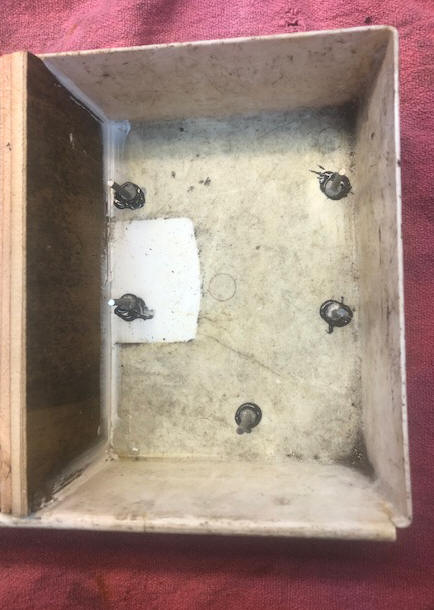
My plan was to find something to use as the bottom of the mold. Here I found a plastic tray, that has slight taper to the sides. It was too wide, so I made and fitted a wooden divider as seen in the LH photo below. Here I needed something to hold the original in a position when pouring the Bondo. This was done by cutting off some 6d nails long enough that when glued to the bottom, they act as a support for the original cover. When done, they will remain in the Bondo mold. Next was to paint release agent on the internal plastic box mold and on the original cover. There was a square notch in it for the choke, and an oval hole where the idle adjustment screw goes in. These were made of a hardwood. They also were coated with a release agent.
In the RH photo below, you can see a felt marker circle on the lower center section. This is for locating a tension spring and will be used during the fiberglassing where I will lay in a washer in that location on top of the fiberglass resin/cloth. It needed a bit of finishing after removing from the plastic box, by filling a few air bubbles with more Bondo, letting that cure and then sanding them down.
| Here is you see my mold box with the stand offs | Here is you see my pretty well finished Bondo female mold |
 |
 |
The original cover was thickened on the back by gluing a 1/16" sheet of fiberglass off a bathroom remodel.
The reason for this is that I am afraid my fiberglass parts need to be thicker than the cast aluminum original and that minimal extra thickness will not interfere. Next was to again, as with the mold, to paint it with release agent.
I started out with the latest (and simplest) version. The early versions has all the instructions cast into the face of this cover. You will notice in the LH photo below, there is a protrusion at the top of the idle needle hole, which is a rotational needle stop.
In making this, the plan is after this female mold is made, to then coat it again with release agent, pour fiberglass resin in, imbed a couple of precut sections of fiberglass cloth. The rear part of this pattern is hid in this photo, so no need to be particular here. And it will be an open female mold for the fiberglass. FYI this late cover, there are aftermarket decals available.
| Here is the front cover with wooden inserts | Here is the back of the thickened cover pattern |
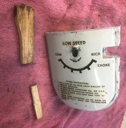 |
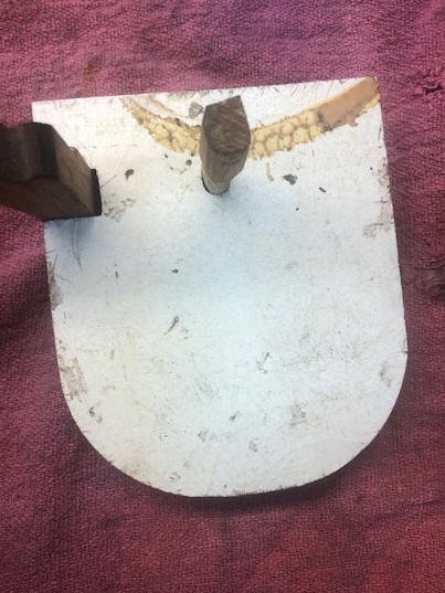 |
As seen in the LH photo below, the first try at laying up a part, this one required considerable effort to remove from the mold. Therefore the mold was later modified by making the outer parts more tapered and therefore easier to remove from the mold. This excess can then be bandsanded off the part after being removed from the mold. The RH photo below shows the original semi-finished part. By that, this one needed some Bondo at least along the lip edges, but after painting and a new decal installed it should be a very good duplicate for a OBSOLETE part.
| Here is the new fiberglass front cover being cast/laid up in the mold | Here the first, semi-final part |
 |
|
Observation ;
It appears (from much research and some guessing) that these motors,
over time have used different propellers. JW10s (Weedless
gearbox) used gearbox gears of 12-20 or a ratio of 1.666. Later
as proven in 1957 the Evinrude #3022 used 17-28 gears or a ration of 1.647.
They also used either a 2 or a 3 blade prop. My research reveilles that the lower gear ratio used a #203120 3 blade prop, Where the higher ratio used a 2 blade #3203919. I also have found the folding weedless motors also having the 17-28 gear ratio, but many times with the 3 blade. ? ?
The prop #203919 was a 2 blade with a dimension of 6 1/4" X 5 1/2 OR 6 1/8" X 6 1/4" pitch depending list on what you read. Prop #203120 was a 3 blade with dimension of 6 1/4" X 5 3/4" pitch. Why the change of the gear ration and the use of different props ?? WHY ??? This weedless unit, being angled as it is cannot accommodate a prop much larger than 6" diameter.
It is my estimation that the early weedless motors (52-54) having the faster gear ratio (1.666) used the 3 blade props, and later motors went to the slightly slower gear ratio (1.647) and the 2 blade (why as the ratios of the gears and the size of the props are miniscule).
The Yachtwin gearbox uses a gear ratio of 12-24 equating to a ratio of 2.00. My research also shows this standard JH gearbox used the 3 blade 8" X 4 1/2" or 8" X 5 1/2".
Back to the Main Ramblings Page
Copyright © 2022 - 2023 LeeRoy Wisner All Rights Reserved
Originated 03-25-2022, Last updated
02-14- 2023
to contact the author click here